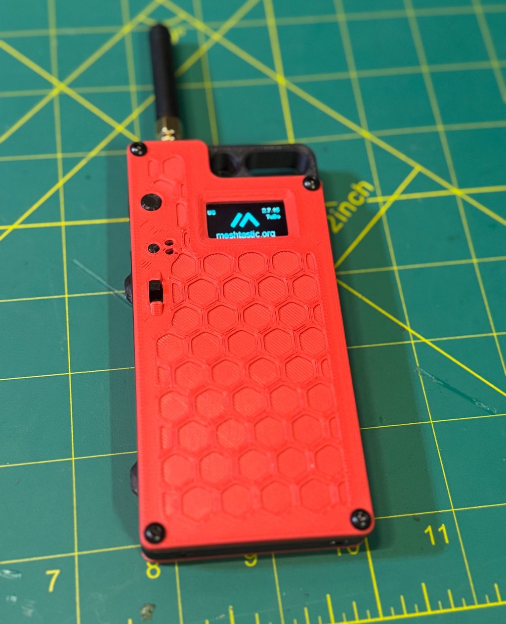
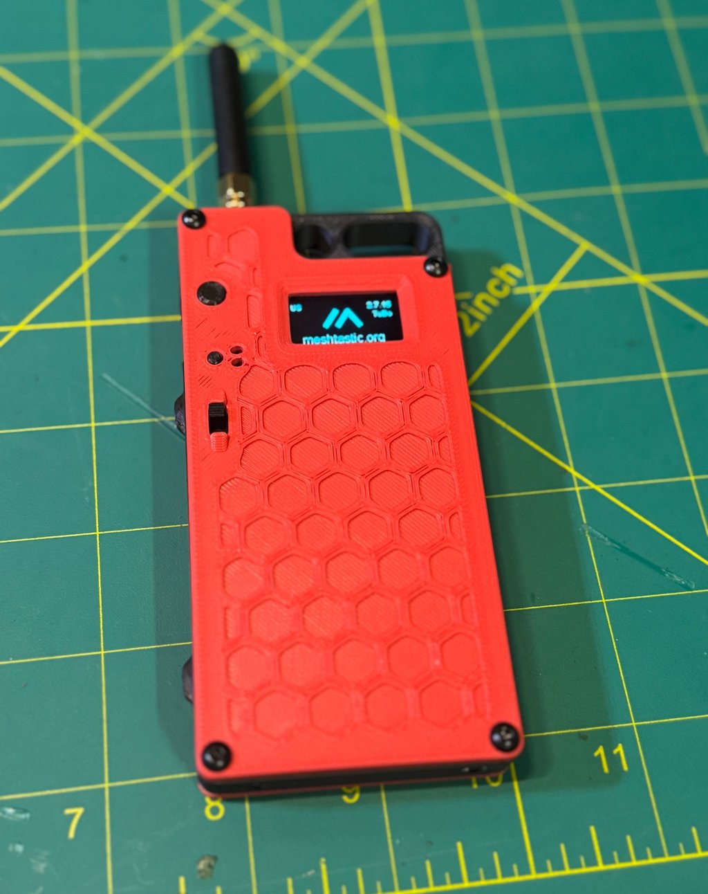
Portable Meshtastic with Heltec V3, 3000mAh battery, and custom 3D print
/PROJECT 26-03/MSG 01/Group project for Winter Field Day building portable Meshtastic nodes to support growth of Meshtastic users in Northern NY
MESHTASTIC
TUX
2/6/20266 min read

/REF/A/"Mestastic Website"/"https://meshtastic.org/"
/REF/B/"Heltec V3 with 3000mAh battery"/"https://www.printables.com/model/1575294-heltec-v3-with-3000mah-battery"
Purpose
The purpose of this project is to design, build, and deploy a battery-powered mobile Meshtastic node as part of a standardized, repeatable architecture supporting resilient, off-grid communications across Northern New York, with initial deployment and group construction occurring during Winter Field Day. This build is intended to function reliably in austere winter conditions without dependence on commercial power, cellular service, or internet connectivity, while serving as a foundational element in a growing regional mesh network that complements existing HF, VHF, and voice-based communications. By using a common hardware and configuration baseline, this project transforms a single build into a scalable infrastructure effort that emphasizes survivability, interoperability, and long-term regional utility rather than a one-time demonstration.
This project is designed to:
Establish a persistent, battery-powered Meshtastic node capable of continuous unattended operation
Support the development of a regional Meshtastic mesh architecture in Northern New York
Enable group-based construction and standardized deployment during Winter Field Day
Provide a low-power digital coordination layer alongside traditional amateur radio operations
Reinforce practical skills in solar power design, RF deployment, and cold-weather hardening
Check out the solar-node build
Build Requirements
MakerFocus ESP32 Lora V3 (https://www.amazon.com/dp/B0DLVVLSZB)
USB-C Cable (borrowed from RAK19003 kit)
915 MHz Antenna (borrowed from RAK19003 kit)
3000mAh Battery (https://www.amazon.com/dp/B08T6GT7DV)
IPEX to SMA pigtail (https://a.aliexpress.com/_mqXWQ3T)
M3 Heat Insert (https://www.amazon.com/dp/B0D7M3LJDL)
M3x6 Button Head (https://www.amazon.com/dp/B01B1OD0IC)
Additional components
[UPGRADE] Switch 3 pin (https://www.amazon.com/dp/B0BRH2SPXV)
3D Print Mounting Components (https://www.printables.com/model/1575294-heltec-v3-with-3000mah-battery)
Tools Required
Screwdriver set
Wire cutters/strippers
Soldering Iron
Solder
Flux
Android/iOS/Computer to program Meshtastic Node
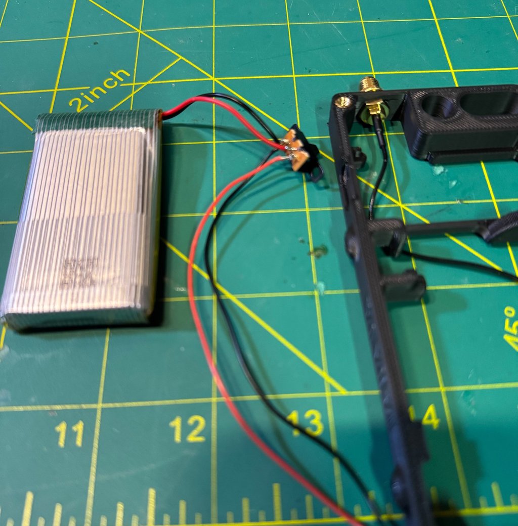
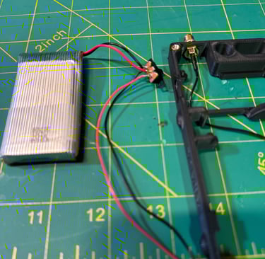
Power Switch Wiring
This step prepares the inline power switch between the battery and the JST 1.5 connector that will interface with the Heltec V3. Begin by grouping both ground (black) wires together on the same side of the switch. Pre-join these two wires with a small amount of flux and solder, then route them through the small hole on the switch lug and give them a quick, clean touch of solder to secure the joint. Next, place the battery positive (red) wire on the center pin of the switch. Finally, connect the positive (red) JST lead to the remaining pin. Using a light pre-flux and pre-solder technique on all wires before final assembly makes this process significantly cleaner and reduces the chance of cold joints or rework. (TEST TO MAKE SURE THE SWITCH ACTUALLY WORKS)
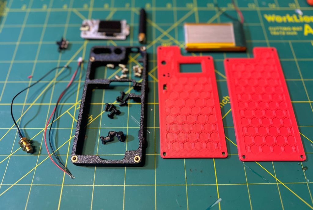
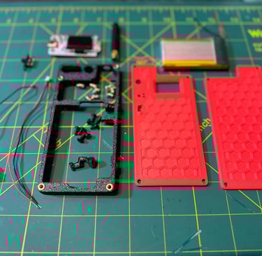
Hardware Installation
With the switch wired, move on to installing the antenna base into the node housing. This is a straightforward push-through and screw-down installation—seat the connector, align it properly, and secure it in place. Next, install the M3 heat-set inserts into the enclosure. Place each insert into its pre-made hole; it should start with a light press fit from one side. Using a soldering iron equipped with a heat-set insert tip, gently press the insert into place. Set the iron temperature to approximately the same temperature used for printing (around 260°C for PLA). Apply slow, even pressure and allow the insert to sink flush without deforming the plastic. Repeat this process for all eight heat-set inserts, ensuring each one is straight and fully seated before allowing it to cool.
Heltec V3 Board Installation
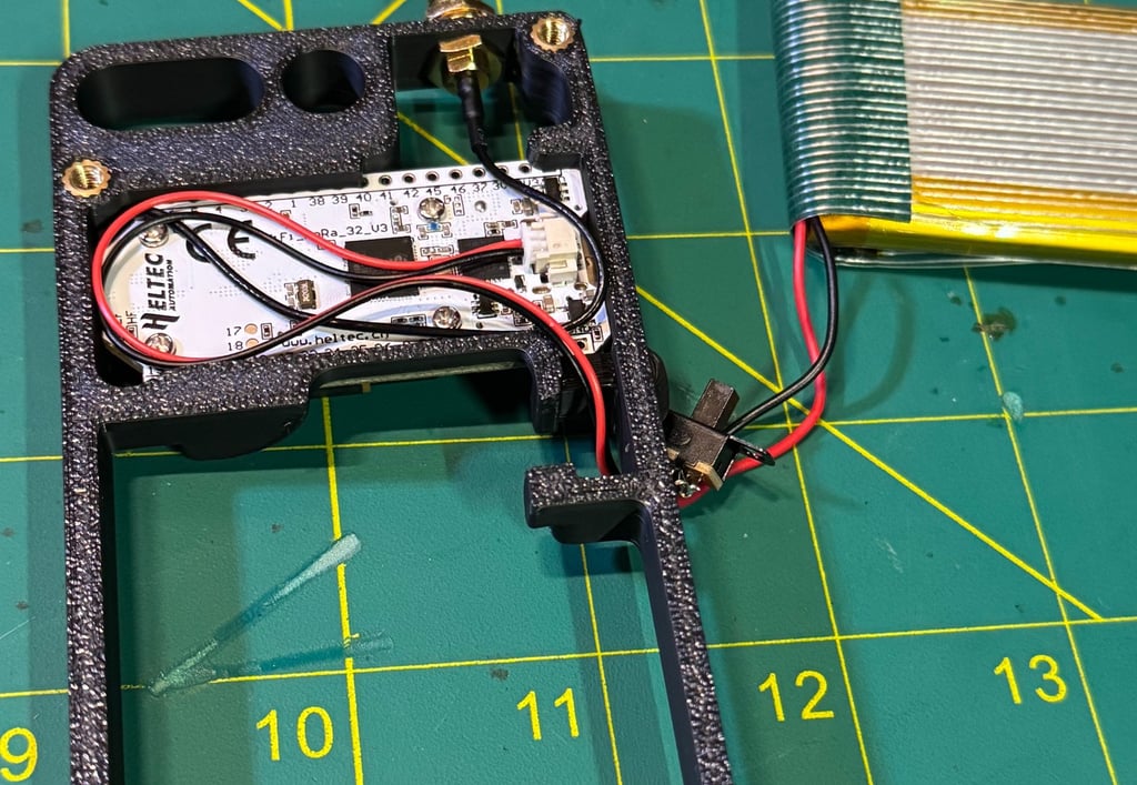
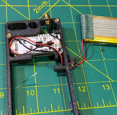
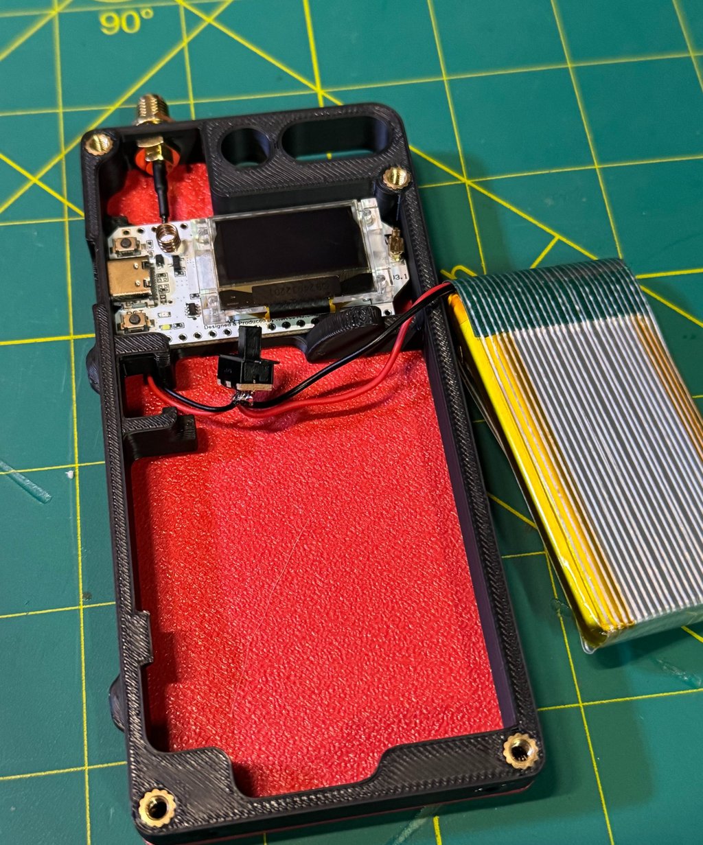
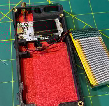
Begin by installing the Heltec V3 board into the enclosure. Before seating the board, connect the IPEX antenna connector first—this is significantly easier to do now than after the board is mounted and saves a lot of frustration later. Once the antenna lead is attached, align the board by lining up the USB-C port with the opening in the enclosure and press the board firmly into place, ensuring it is fully seated. Take care to route the antenna cable along the sides of the enclosure so it is not pinched or trapped beneath the board.
After the board is seated, attach a temporary antenna to the antenna base for testing and handling. Next, connect the JST power connector to the Heltec board, then route the power and switch wiring through the provided cable slots as shown in the enclosure design. Finally, move the battery and power switch out of the immediate work area, leaving them accessible but clear of the board, in preparation for final wiring, testing, and enclosure closure.
Backplate, Battery, and Switch Installation
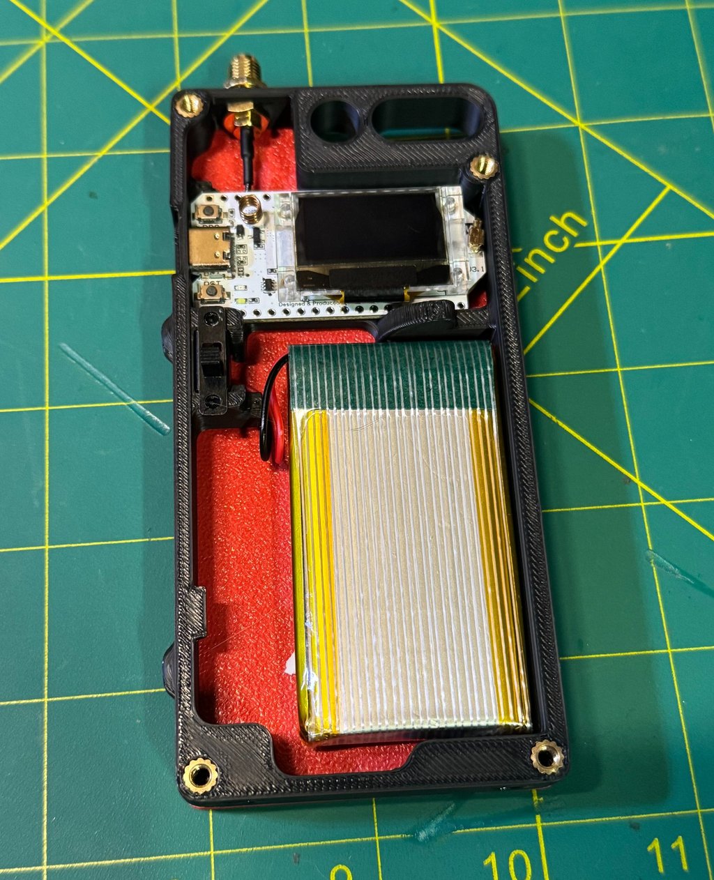
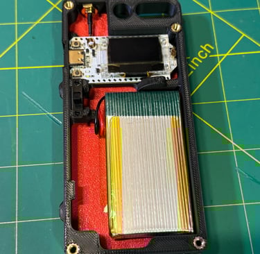
With all wiring routed clear, install the backplate for the board. Using the M3×6 screws, secure the backplate in place while carefully verifying that no wires are pinched or trapped between the board, backplate, or enclosure. Tighten the screws evenly to keep the assembly square and stable.
Next, position the battery and power switch in their designated locations within the enclosure. If the switch needs additional retention, lightly touch the surrounding PLA with a soldering iron to soften it just enough to mold around the switch’s metal retention clips—this helps lock it in place without additional hardware. (MAKE SURE THE SWITCH IS IN THE CORRECT ORIENTATION) To prevent movement during transport or field use, apply a small amount of double-sided tape to the battery before seating it, ensuring it remains secure and does not shift inside the case.
Closing it up
To complete the physical assembly, install the front plate. Begin by placing a small piece of electrical tape over the printed buttons to temporarily hold them in position against the plate—this makes alignment much easier during installation. With the buttons retained, carefully set the front plate onto the node, ensuring all buttons, ports, and cutouts are properly aligned. Once everything is seated correctly, install the final screw and snug it down to secure the front plate in place.
Flash Board
Navigate to flasher.meshtastic.org, select Heltec V3. Connect the board to your computer using USB-C. Select your firmware version and click "Flash". This is the rodeo of selecting the corrct USB that pops up during flashing. Allow about a minute for the board to complete flashing and reboot.
Once rebooted, go to client.meshtastic.org, connect to the board by selecting the correct COM port (use Device Manager if needed, or unplug and reconnect the board while the selection window is open).
At a minimum, verify the Bluetooth PIN under Bluetooth settings and set the correct country/region under the LoRa tab. Save and send the configuration to the board and allow it to reboot, then disconnect the USB cable.
Node Settings
This isn't a tutorial on setting up a Meshtastic node and all the intricate details, but I will provide how I will be setting this node up. Would love to hear recommendations and how to better improve this. The order is based on how I see it in the Web Browser.
Radio Config
Node Broadcast Interval - 10800 (I set all my times to 3 hours until I do testing to make it longer)
Fixed Position - Enabled (when I emplace this, I will use an Android to type in the actual grid of the location)
Broadcast Interval - 10800
Enable Power Saving Mode - Enabled
Module config
OK to MQTT - Enabled
Bluetooth Fixed Pin - Unique Pin
Primary and Secondary Admin Key - Key for devices that can remote manage
MQTT Enabled - Default creds
Root Topic - msh/US/NY
Map Reporting Enabled - Enabled
Map Report Publish Interval - 10800
Approximate Location - 1.5km or 1.8 miles (has to be this broad or higher to report to meshmap)
Module Enable Store and Forward - Enabled
Device Metrics - 10800
Power Measurement Enabled - Enabled
Channel Config
Default Primary Channel
Uplink Enabled - Enabled
Within 1.5km
Channel 1
PSK and Name of private network
Change Device Name - BE CREATIVE!
#Meshtastic #LoRa #LoRaMesh #OffGridComms #MeshNetworking #SolarPowered #LowPower #PacketRadio #AmateurRadio #HamRadio #ARRL #WinterFieldDay #FieldDay #K2FTS #NorthernNY #NorthCountry #NYComms #CommunityComms #DIYElectronics #Makers #3DPrinting #EmbeddedSystems #WisBlock #RAKWireless #EmergencyComms #ResilientComms #AustereOperations #DisasterPreparedness #GridDown #TacticalComms #FieldDeployable