
Harbor Breeze Solar Light with Rak Wireless RAK19003 for Meshtastic Build
/PROJECT 26-02/MSG 01/Group project for Winter Field Day building solar nodes to support growth of Meshtastic users in Northern NY
TUX
1/23/20266 min read
/REF/A/"Mestastic Website"/"https://meshtastic.org/"
/REF/B/"RAK19003 WisBlock Mini Base Board Datasheet"/"https://docs.rakwireless.com/product-categories/wisblock/rak19003/datasheet/"
Purpose
The purpose of this project is to design, build, and deploy a solar-powered Meshtastic node as part of a standardized, repeatable architecture supporting resilient, off-grid communications across Northern New York, with initial deployment and group construction occurring during Winter Field Day. This build is intended to function reliably in austere winter conditions without dependence on commercial power, cellular service, or internet connectivity, while serving as a foundational element in a growing regional mesh network that complements existing HF, VHF, and voice-based communications. By using a common hardware and configuration baseline, this project transforms a single build into a scalable infrastructure effort that emphasizes survivability, interoperability, and long-term regional utility rather than a one-time demonstration.
This project is designed to:
Establish a persistent, solar-powered Meshtastic node capable of continuous unattended operation
Support the development of a regional Meshtastic mesh architecture in Northern New York
Enable group-based construction and standardized deployment during Winter Field Day
Provide a low-power digital coordination layer alongside traditional amateur radio operations
Reinforce practical skills in solar power design, RF deployment, and cold-weather hardening
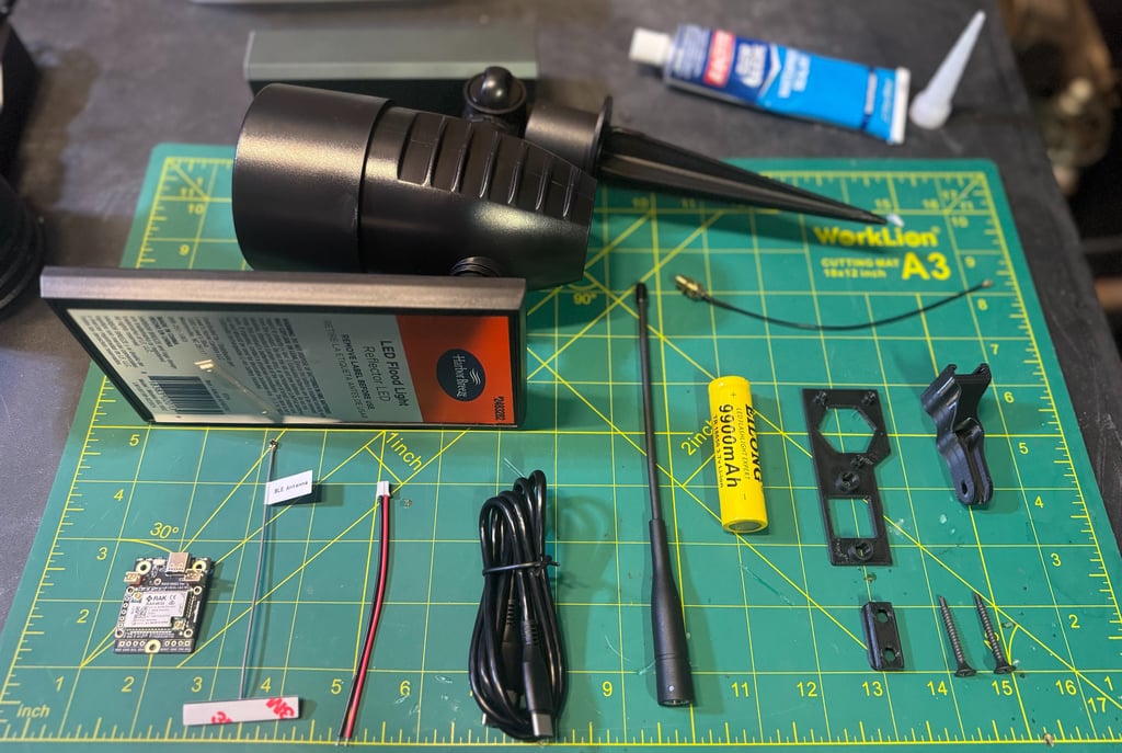
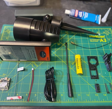
Build Requirements
RAK Wireless RAK19003 board with RAK4630 (https://store.rokland.com/products/rakwireless-mini-meshtastic-starter-kit-us915-rak19003-4631-sku-115093)
BLE Antenna (included in RAK19003 kit)
JST 2.0 connector //WARNING//READ ABOUT CHANGING INPUTS (https://www.amazon.com/dp/B088NFRNZ2)
USB-C Cable (included in RAK19003 kit)
[UPGRADE] 915 MHz Antenna (https://www.amazon.com/dp/B0DPSB5F8R)
Harbor Breeze Solar Light (https://www.lowes.com/pd/Harbor-Breeze-60LM-Solar-Flood-Light-0-6-Watt-Black-Solar-LED-Flood-Light/1002689960)
[UPGRADE] IPEX to SMA pigtail (https://a.aliexpress.com/_mqXWQ3T)
Additional components
[UPGRADE] 18650 Battery 9900 mAh (https://www.amazon.com/dp/B0BRH2SPXV)
3D Print Insert (https://www.thingiverse.com/thing:6849930)
3D Print Mounting Components (https://www.printables.com/model/886187-harbor-breeze-meshtastic-mount)
Insert Screws (included in RAK19003 kit)
Mounting Screws
Tools Required
Screwdriver set
Wire cutters/strippers
Silicone Waterproof Sealant
Soldering Iron
Solder
Flux
Android/iOS/Computer to program Meshtastic Node
Disassemble
This section covers the initial disassembly of the Harbor Breeze solar light used as the donor enclosure and solar assembly for this build. The objective is to fully separate and remove the factory lighting components while preserving the solar panel, housing, and critical hardware for reuse.
Begin by unscrewing the cap on the front of the light, which provides access to the internal wiring for the LED assembly; once exposed, cut the two wires leading to the light to electrically isolate the LED.
Next, separate the solar housing from the main light housing by removing the single metal screw securing the two halves—this screw must be retained for later reassembly. With the screw removed, the previously cut wires should pull freely out of the light housing.
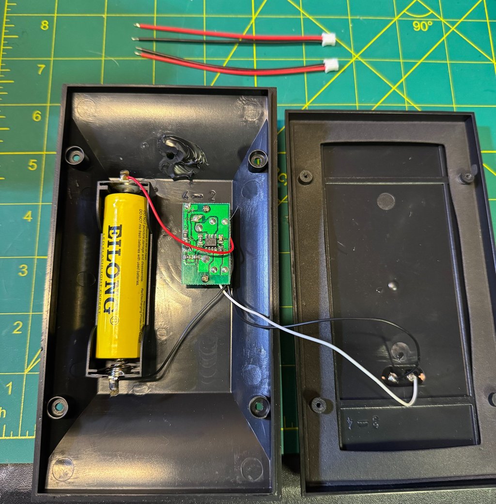
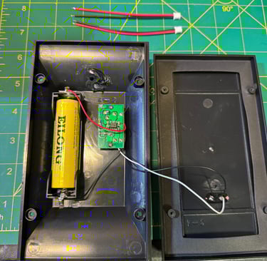
Move to the solar housing and remove the four small screws on the back, then carefully open the housing like a book to expose the internal circuit board and wiring. Finally, snip the remaining light wires as close to the circuit board as possible and completely remove them from the housing, leaving only the solar panel leads and internal electronics intact for integration into the Meshtastic node.
Power Assembly
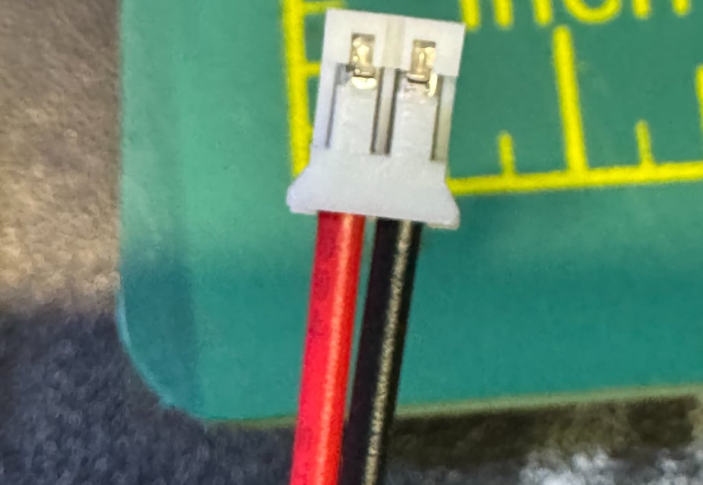
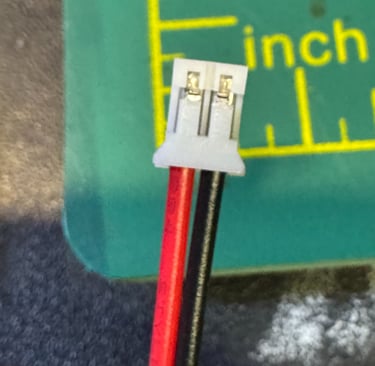
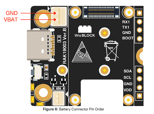
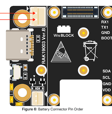
The JST 2.0 cables provided are wired in reverse and must be corrected to match the polarity shown in the RAK19003 WisBlock Mini Base Board datasheet before connecting any power source. To reverse the wiring, carefully lift the small plastic retention tab on the JST connector (a razor blade or fine pick works well) and pull the metal pin and wire straight out. Once removed, reinsert the pin into the opposite slot until it clicks and is securely retained.
After correcting the connector orientation, solder the JST leads to the battery terminals, ensuring polarity is correct—this step is color coordinated, but verify before applying heat. A small amount of flux is strongly recommended to ensure a clean, reliable solder joint.
Once soldered and inspected, you may optionally replace the stock 1500 mAh battery with a 9900 mAh battery to significantly extend runtime and improve resilience during low-sun winter conditions.
Install 3D Printed Components
Begin by removing the charge controller from the solar housing by backing out the two mounting screws and setting the controller aside. Take the RAK housing insert and slide it underneath the charge controller, aligning it with the existing screw hole guides molded into the housing. Once seated correctly, reinstall the charge controller using the original screws, securing both the controller and the insert at the same time—do not install the RAK board yet.
Next, connect the JST power connector to the mounting hardware, ensuring it is fully seated and strain-relieved. Feed the IPEX antenna connector through the existing hole in the solar housing, taking care not to kink or stress the cable.
Finally, use the original metal screw retained during disassembly to secure the mounting hardware to the solar housing, locking the entire assembly in place and ready for board installation in the next step.
Flash Board
Navigate to flasher.meshtastic.org, select RAK WisBlock 4631, and download the firmware file. Connect the RAK board to your computer using USB-C, then double-click the RST button on the board to place it into DFU mode. A new removable device will appear in Windows File Explorer; drag and drop the downloaded firmware file into this folder to flash the board (if you're using Linux or MAC or DOS or whatever you're using, you should figure this out on your own). Allow about a minute for the board to complete flashing and reboot.
Once rebooted, go to client.meshtastic.org, connect to the board by selecting the correct COM port (use Device Manager if needed, or unplug and reconnect the board while the selection window is open).
At a minimum, verify the Bluetooth PIN under Bluetooth settings and set the correct country/region under the LoRa tab. Save and send the configuration to the board and allow it to reboot, then disconnect the USB cable.
Board Assembly
After flashing and configuration, connect the IPEX connector for the LoRa antenna to the LoRa port on the board and attach the 915 MHz antenna to the SMA connector.
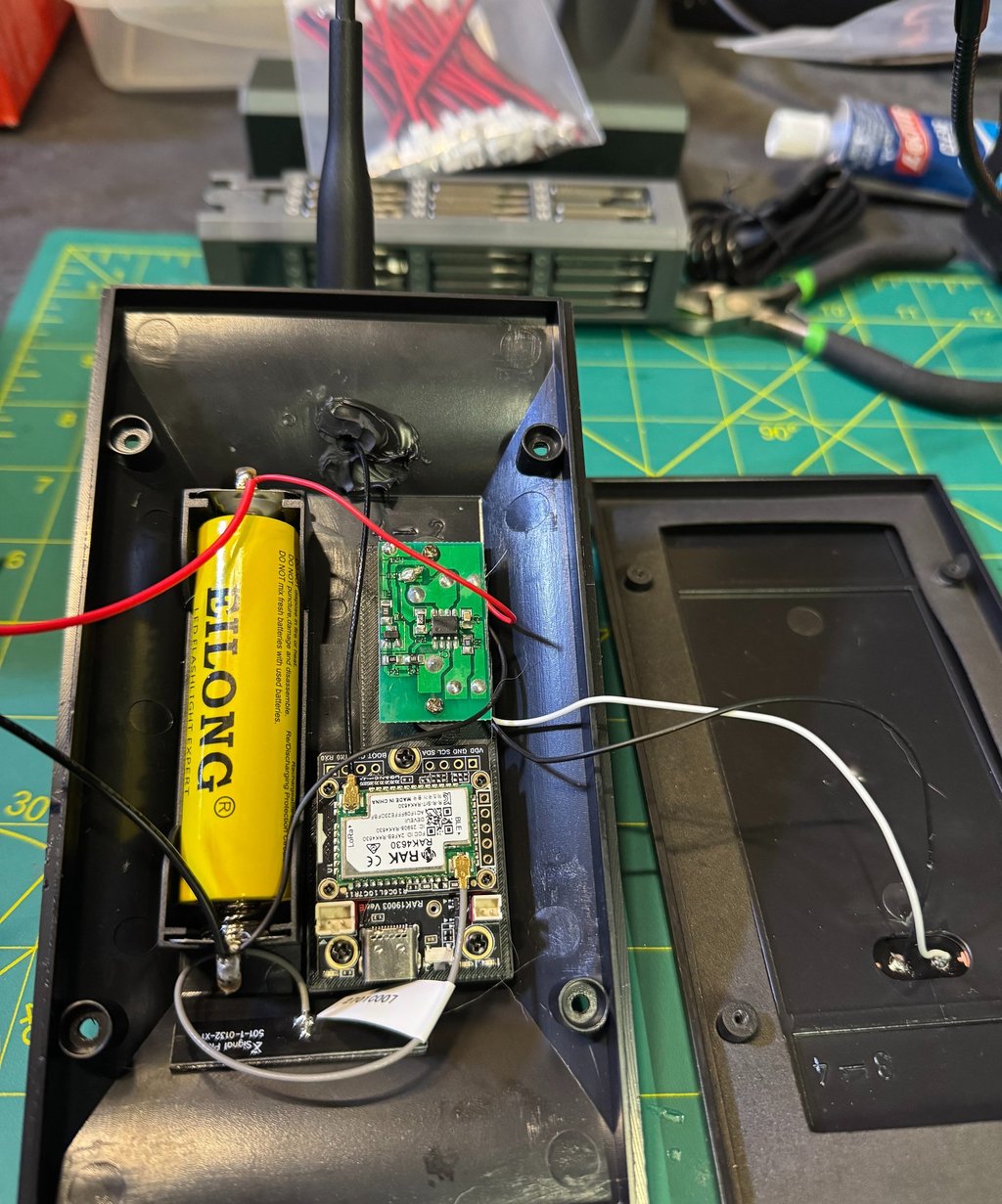
Next, connect the provided Bluetooth antenna to the BLE port and secure it inside the housing (taped in place as needed, using the screws provided with the hardware set). Mount the RAK board onto the insert adapter inside the solar housing, then connect the IPEX cables to the LoRa and BLE ports.
With all antennas secured and wiring verified, plug the JST power cable into the node—the system is now fully assembled and ready for final enclosure closure and deployment.
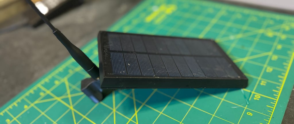
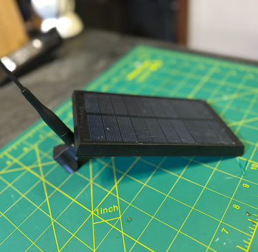
Closing it up
With all internal components installed, begin closing the enclosure by confirming the node has successfully booted—you should observe flashing status LEDs on the RAK board indicating normal operation.
Before sealing the housing, verify Bluetooth connectivity by connecting to the node using the Meshtastic mobile app on your phone.
Once connectivity is confirmed, apply a small dab of waterproof sealant around the hole where the IPEX connector passes through the enclosure to restore environmental protection.
Carefully guide all wiring into the housing, ensuring no cables are pinched or under strain, then bring the two halves of the enclosure together. Reinstall the four housing screws to fully reassemble the unit, tightening them evenly to maintain a proper seal.
At this point, the node is mechanically complete and powered—proceed to remote programming and network configuration for final deployment.
Node Settings
This isn't a tutorial on setting up a Meshtastic node and all the intricate details, but I will provide how I will be setting this node up. Would love to hear recommendations and how to better improve this. The order is based on how I see it in the Web Browser.
Radio Config
Node Broadcast Interval - 10800 (I set all my times to 3 hours until I do testing to make it longer)
Fixed Position - Enabled (when I emplace this, I will use an Android to type in the actual grid of the location)
Broadcast Interval - 10800
Enable Power Saving Mode - Enabled
Module config
OK to MQTT - Enabled
Bluetooth Fixed Pin - Unique Pin
Primary and Secondary Admin Key - Key for devices that can remote manage
MQTT Enabled - Default creds
Root Topic - msh/US/NY
Map Reporting Enabled - Enabled
Map Report Publish Interval - 10800
Approximate Location - 1.5km or 1.8 miles (has to be this broad or higher to report to meshmap)
Module Enable Store and Forward - Enabled
Device Metrics - 10800
Power Measurement Enabled - Enabled
Channel Config
Default Primary Channel
Uplink Enabled - Enabled
Within 1.5km
Channel 1
PSK and Name of private network
Change Device Name - BE CREATIVE!
#Meshtastic #LoRa #LoRaMesh #OffGridComms #MeshNetworking #SolarPowered #LowPower #PacketRadio #AmateurRadio #HamRadio #ARRL #WinterFieldDay #FieldDay #K2FTS #NorthernNY #NorthCountry #NYComms #CommunityComms #DIYElectronics #Makers #3DPrinting #EmbeddedSystems #WisBlock #RAKWireless #EmergencyComms #ResilientComms #AustereOperations #DisasterPreparedness #GridDown #TacticalComms #FieldDeployable